
TM 5-3990-263-13&P
0052
DISASSEMBLY - Continued
5
6
40
38
39
3
40
38
43
42
41
5
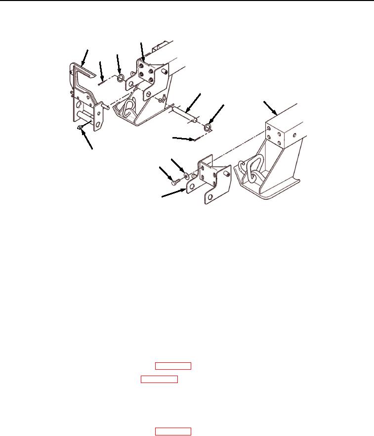
Figure 5. BAP Front Pin Disassembly.
14.
Remove pin lock guide (Figure 5, Item 6) from pin lock bracket (Figure 5, Item 5).
15.
Remove four screws (Figure 5, Item 41) and washers (Figure 5, Item 42) from pin lock bracket (Figure 5, Item
5).
16.
Remove pin lock bracket (Figure 5, Item 5) from frame (Figure 5, Item 3).
NOTE
Perform Step (17) if grease fitting is damaged.
17.
Remove grease fitting (Figure 5, Item 43) from pin lock guide (Figure 5, Item 6).
END OF TASK
CLEANING
1.
Refer to General Maintenance Instructions (WP 0038) for general cleaning instructions.
2.
Lubricate all pins in accordance with (WP 0070).
END OF TASK
INSPECTION
1.
Refer to General Maintenance Instructions (WP 0038) for general inspection instructions.
2.
Measure wear pad (Figure 6, Item 1). If wear pad (Figure 6, Item 1) is worn to within 1/16 inch (1.6 mm) of
screw (Figure 6, Item 2) or pin lock jaw (Figure 6, Item 3), wear pad (Figure 6, Item 1) can be rotated 180
degrees and reused. If bottom and top edges of wear pad (Figure 6, Item 1) show excessive wear, replace
wear pad (Figure 6, Item 1).
03/15/2011Rel(1.8)root(maintwp)wpno(M04047)