
TM 5-3990-263-13&P
0052
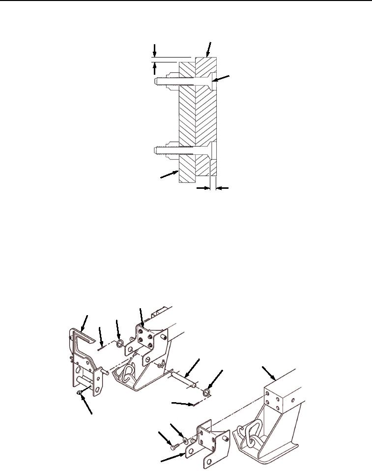
INSPECTION - Continued
1
1/16 INCH
2
3
1/16 INCH
Figure 6. BAP Front Pin Lock Assembly Inspection.
END OF TASK
ASSEMBLY
NOTE
Perform Step (1) if grease fitting was removed.
1.
Install grease fitting (Figure 7, Item 43) to pin lock guide (Figure 7, Item 6).
5
6
40
38
39
3
40
38
43
42
41
5
Figure 7.
BAP Front Pin Assembly.
03/15/2011Rel(1.8)root(maintwp)wpno(M04047)